Configuration
The following steps will show you how to prepare a Smart DWG Exporter configuration and define which information about the objects should be contained in the AutoCAD drawing file.
STEP 1:
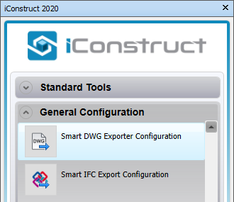
Go to General Configuration tab in the iConstruct menu and click Smart DWG Exporter Configuration button.
STEP 2:
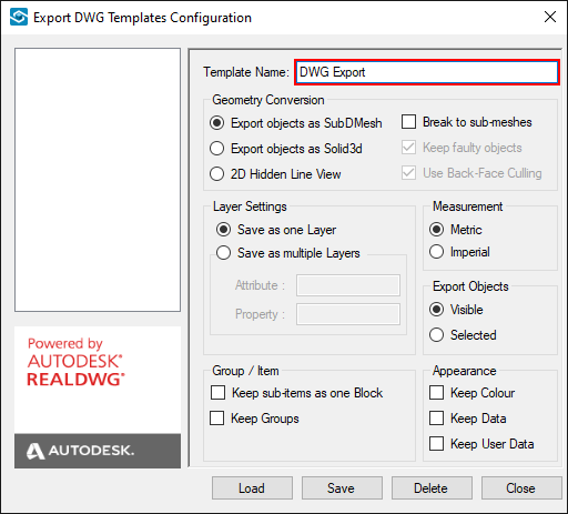
Type in a Template Name of your configuration (DWG Export in our example).
STEP 3:
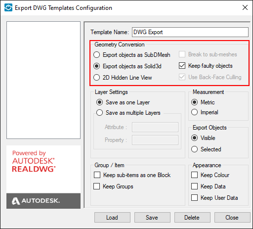
Define Geometry Conversion by selecting one of the three options. Objects in the DWG file could be created as SubDMesh, Solid3d objects or as flatten mesh - 2D Hidden Line View (Top View).
Note: If Solid3d is selected as the output format of the objects, processing the model could take more time. Also the produced file would be significantly bigger than SubDMesh format.
STEP 4:
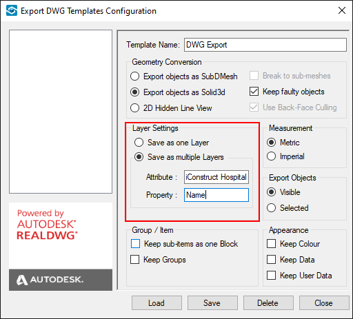
Select Layer Settings. You can either save every object as one Layer or group objects in different layers based on Attribute/Property values of each object.
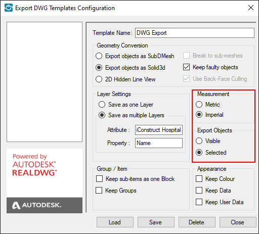
STEP 5:
Set the drawing file measurement unit and define Export Objects. You can export just Visible elements or Selected.
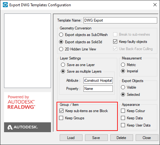
STEP 6:
Each segment of an item in Navisworks model could be divided into multiple objects based on the complexity of the item geometry. By enabling these options different items could be saved as one block in the DWG file.
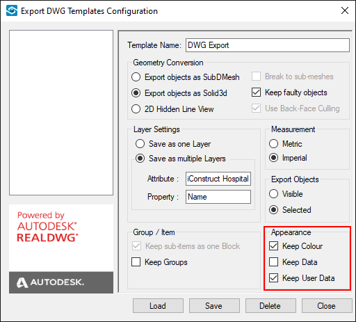
STEP 7:
Select Appearance options. Keep Colour will store the current visible attributes (Colour) of the object in the produced DWG file. Keep Data stores all property data of an item as an XData in the DWG file. Selecting this option automatically results in enabling the Keep sub-items as one Block as Navisworks properties are under one segment.
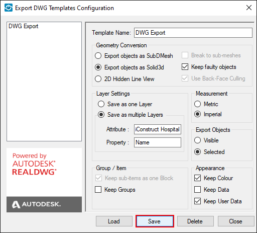
STEP 8:
Click Save and Close the dialogue box.
Quick Overview:
➤ Go to Smart DWG Exporter Configuration ➤ Define a Template Name ➤ Choose a Geometry Conversion ➤ Select Layer Settings ➤ Define units and Export Objects ➤ Select block creation ➤ Define Appearance ➤ Click Save